We used a host of adapters to split the 3.5mm jack into two separate connectors: one for audio and one for video. As a result, standard cables that breakout 3.5mm to stereo audio and video do not work because the ground is not properly shared. However, on the Raspberry Pi, the mapping is left audio, right audio, ground, video signal. The four pins from tip to sleeve are usually mapped as left audio, right audio, video signal, ground. The video signal allows for composite video which is what our screen uses. The 3.5mm jack is actually a four port jack that is capable of outputting an additional video signal. If a speaker cable is plugged into this port, the system immediately outputs audio given that the audio signals for stereo output are left, right, and ground. The Raspberry Pi PCB contains a 3.5mm jack. The joystick and main six arcade buttons on the front of the cabinet are soldered to a perf board with a header, the two side buttons and the two debug buttons at the top of the arcade are on a separate perf board with a header, and both of these headers interface with the Raspberry Pi through a breakout on a perf board.VIDEO AND SOUND We set out to make the system as modular as possible to make the system easier to methodically debug. FunctionĪfter a mapping was decided upon, connectors were soldered and crimped to connect the various peripherals to the Raspberry Pi. The final mapping for the joystick and arcade button peripherals is shown below. Each button within the joystick featured the same pinout as the arcade buttons. We used the active-low and ground pins so that pressing a button would drive the input pin to the Raspberry Pi low and trigger a falling-edge callback event within our Python program. The arcade style buttons have three pins designations: ground, active-low, and active-high. Two small buttons hidden at the top of the system’s housing contain two pins each. Overall, we are satisfied with the sturdiness, durability, and general ergonomics of our final design, which we believe offers a comfortable and entertaining gameplay experience.Īll of the buttons and joystick controls are mapped to GPIO input pins on the Raspberry Pi.

Using the Autodesk Inventor suite, we constructed a 3D model and each face of the different arcade station housing were put into one template file to be created with a laser-cutter. keyboard and mouse), as well as access the micro-SD card.CADĪll of the modeling for this project was done by us. It does, however, allow the user to plug in USB devices (i.e. The entire system is fully self-contained and doesn’t require any other peripherals to operate. The speakers are repurposed desktop speakers that have been stripped of their casing: only the electronics from the speakers have been included in the arcade station housing. The joystick and buttons mimic those of classic arcade machines. The 7 inch screen intended for use within cars as a rear view camera. The hardware components of the system include the screen, joystick, buttons, speakers, the laser-cut frame, and the Raspberry Pi. In the main menu of the system, one can read an ‘About’ section listing out the developer names, launch the pre-built EmulationStation to play classic game ROMs, play any of the three games we built, view the high scores for our pre-built games, and cleanly shut down the system. While working on top of this pre-built image, we made three of our own Python games. The GPIO button inputs to the Raspberry Pi are mapped to a virtual gamepad which can be used to manipulate menu screens and perform actions within the custom-build games and ROMs. Within these emulators, we pre-loaded a sampling of classic video game ROMs. Within this menu screen, the user can launch a pre-built EmulationStation which can run emulators of classic systems like the Nintendo Game Boy, NES, SNES, and much more.
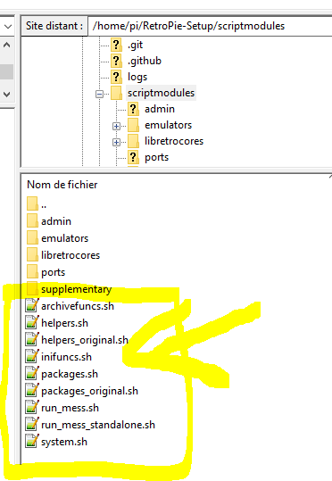
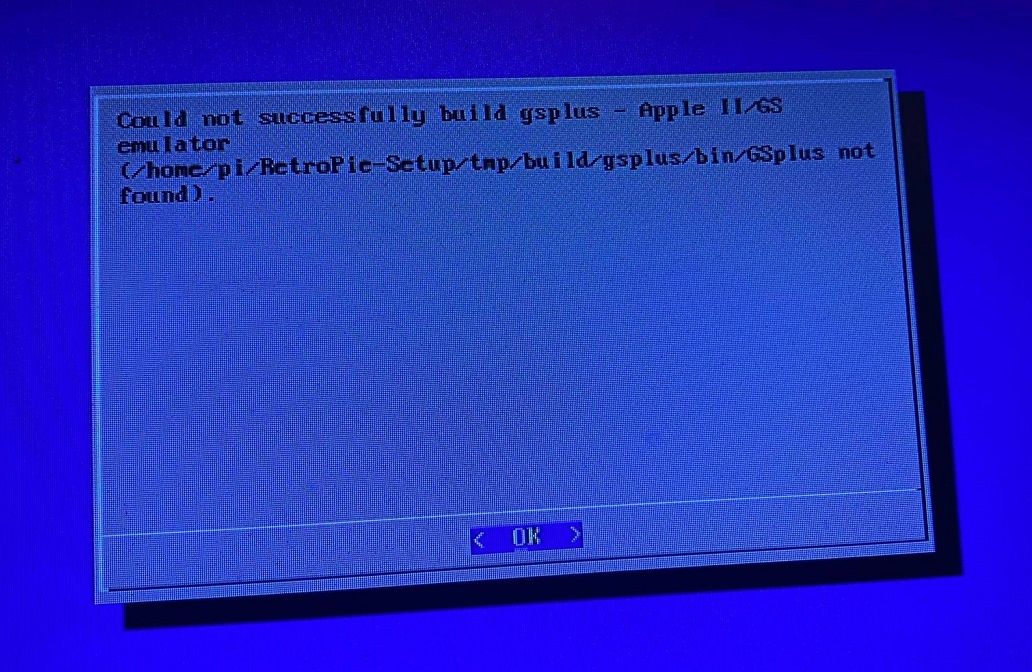
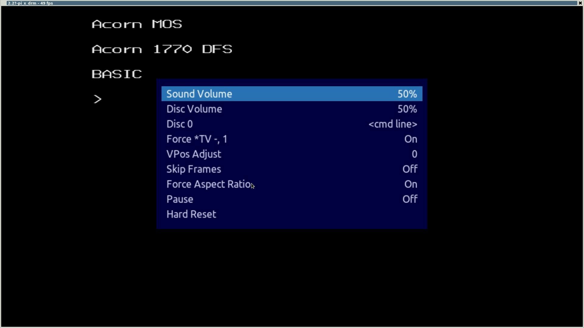
How to use retropie scriptmodules software#
On the software side, we created a menu screen that launches on bootup of the system. Finally, the 3.5mm jack needed to be broken out so that all four connection points were exposed and could be spliced into separate connectors to produce composite video for the screen as well as a stereo output for the speakers.

All of the buttons and the joystick needed to have their leads crimped and soldered in order to cleanly interface with the GPIO pins of the Raspberry Pi. On the hardware side, the entire cabinet needed to be designed, laser-cut, and assembled with the purchased arcade peripherals. This project has extensive hardware and software aspects that were developed concurrently.


Figure 1: Raspberry Pi Arcade Station INTRODUCTION


 0 kommentar(er)
